Wednesday, October 7, 2009

The Complete Clapper Circuit (07.10.2009)


After soldering, the Clapper Circuit is completely done. Testing on the circuit had proven that the it is well functioned.

Some measurements are taken for analysis. The information that we take noted will be written in the final report.

The video uploaded shows the complete Clapper Circuit. For last time, we clap once to either switch on or off the LED. But the truth is, we must clap twice in order to switch the LED on or off. Similarly, further details will be presented in our final report on the Clapper Circuit.

Tuesday, October 6, 2009

Soldering (6.10.2009)

We finally can soldering by today after transferred all the components to copper strip board. But before that, we need to drill several drains first at copper strip board to separate the nodes especially for components like IC and relay. We also done certain part of our report except testing and result's part.

Monday, October 5, 2009

Transfer component to copper strip board(5.10.2009)


Today,we try to measure and observe the waveform of microphone.But after we clapped to switch on the LED,the waveform of the microphone appears for a very short time and disappear.
We also try to transfer the component from the breadboard to copper strip board.But we cannot finish it by today because store for socket IC 14 pins finished already.

Friday, October 2, 2009

A Functioned Clapper Circuit (02.10.2009)


Figure 0210/1 
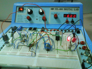
The functioned Clapper Circuit

After a hard try on constructing the circuit, we finally come out with a functioned one. Again, proved that our hypothesis where adding a LED as output between the 2N2222 Transistor and R11 is true.

We had our measurements on the voltage across the lighten LED. It shows that the LED used approximately 3V to function. We also had a try on observing the waveform across the LED, the waveform is shown as below, which is full of noises. We are not sure whether the waveform performed is true or not. Further study on the waveform will be done.


Figure 0210/2 Observing the waveform across the LED.


Figure 0210/3 Waveform performed.
Below is the video on how the Clapper Circuit functions. When the signal (soundwaves) is given, the microphone receives the signal and send it to the 741 OP-Amp, 555 Timer and 4013 Dual D Flip-flop to process. After then, the SPST REED Relay which act as the switch will be connected to lighten the LED. Another signal is then given to switch off the LED. Further study on how these components work in the circuit will be done and presented in our report.

Thursday, October 1, 2009

First Try On Constructing The Circuit ( 01.10.2009 )

Today, we had finally come out with our circuit. We faced an obstacle that is how are we going to know whether the circuit is well functioned. The circuit diagram given in the question is simply the Clapper Circuit without an output. After a discussion, a hypothesis is suggested, which is the output, a LED should be placed between the 2N2222 Transistor and R11. The SPST REED Relay 5V DC Coil act as a switch in this circuit. When the signal reaches the relay, the switch is connected, the current passes through the Relay and R11 causes the LED to light. As the LED is on, we know that the circuit had functioned well. Though, this is just our hypothesis, whether it is correct or not, we will prove by simulate.

The another problem is, we can't get the Relay to be inserted into the circuit because we do not know the way to connect each pin to the corresponding components. Therefore, we are now searching more information about the structure of the Relay, so that we can connect the right parts to the right pins.

Further more, we get some important information on how the 555 Timer and 4013 Dual D Flip-flop work in the circuit. These information helps a lot in understanding the concept of the Clapper Circuit.

In a nut shell, today, we focus more on information searching in order to ease further jobs in the project.

Wednesday, September 30, 2009

Objective and Sub-Objective

The main objective we do our research on the Clapper Circuit is to find out how the Clapper Circuit functions.

Whereas,

The sub-objective of us is to:
a) Learn the functions of the important components that builded up the Clapper Circuit.
b) Enhance our problem solving skills as in information searchinig, compiling, hands-on working and etc..

Introduction to Clapper Circuit

The Clapper Circuit is basically a sound-activated switch sensitive to hand clapping. To switch on and off the appliance which is connected to the circuit, we clap. The sound produces may cause the circuit to function and switch on or off the appliance.

Inside the Clapper Circuit, it has an audio amplifier. The amplifier act as a filter where it has a limiter on the audio signals input. For example, any audio signals that are below a particular thresold will not get through.

When the signal reaches certain pressure level, it triggers the amplifier and swtiches on the appliance. This signal is known as the on signal.